USB Interface
Version A 1.1
Schematic of the USB interface is shown on the picture below.
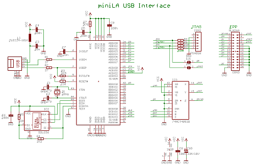
USB interface uses chip FT2232C from FTDI. Connection is recommended USB Bus powered configuration. The chip is configured to work in MCU Host Bus Emulation Mode. This mode is converted to EPP protocol by multiplexer IC3. Because direct decoding of signals /DST, /AST and RD/WR might have timing problems, supplementary signal A8 is used and acts as a RD/WR signal during EPP data phase.
JTAG connector CON2 is for CPLD reconfiguration. It is for future development and is not currently supported
EEPROM IC2 stores the configuration of the FT2232C. This EEPROM must be for correct functionality of the interface programmed. See program MPROG on FTDI website.
Drivers for FTDI USB chip are also available on FTDI website.
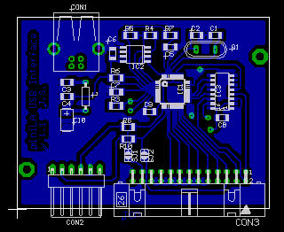
PCB of the interface shown on the picture above uses dual-layered PCB. Since there are only 6 vias the PCB can be made at home with vias replaced by wires.
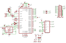
Version B 1.0
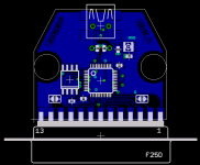
USB interface also exists in version B. This version uses different PCB layout. It does not have separate JTAG connector and it fits into CANNON 25 connector cover.
Pictures
Pictures of version A 1.0
) top side |
) bottom side |
Pictures of version B 1.0
) bottom side |
) top side + cover |
) side view |
) top view |
Downloads
Schematic - version A 1.1: ![]() PDF
PDF
Whole package (schematic, device placement, Gerber, Excellon and PS data for PCB) - version A 1.1: ![]() ZIP
ZIP
Schematic - version B 1.0: ![]() PDF
PDF
Whole package (schematic, device placement, Gerber, Excellon and eagle data for PCB) - version B 1.0: ![]() ZIP
ZIP
Content of the EEPROM (MPROG template): ![]() ZIP
ZIP
FT2232C datasheet: ![]() PDF
PDF